Build your Wdeck.
20 steps from printed parts to your first layout — about two hours of work plus printing time.

What you will do.
Twenty short steps: gather the parts, assemble the hardware, then set up the software. Your place is saved, so you can come back to any step.
- Preparation — parts, tools and a clear desk.
- Hardware build — print, mount, wire, calibrate.
- Software setup — install the app and learn the key types.


Four tools, that is all.
Clear some space and keep the screen face down on something soft while you work.
 Soldering ironHandheld or station, around 320 °C
- ScrewdriverPhillips head, for steps 6 and 8
 Hook-up wireInsulated or solid core, a few colours
 USB data cableMicro-USB or USB-C, not charge-only

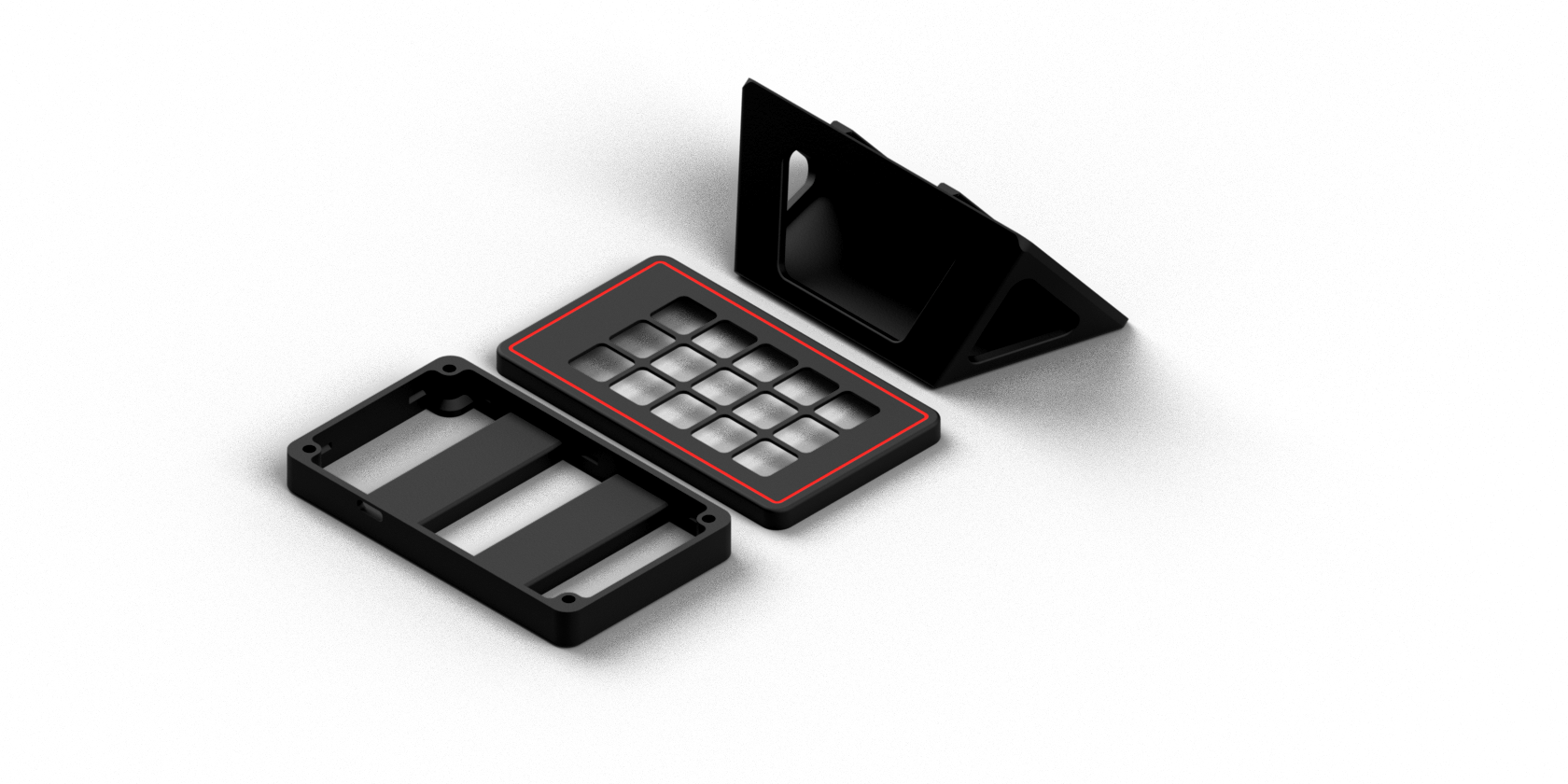
Print the three parts.
Use PETG for heat resistance and durability. Each part can be a different filament.
- Layer height 0.2 mm
- Infill 20 % gyroid
- Supports on the build plate only
Glue the ESP32 into the shell.
Line the micro-USB or USB-C connector up exactly with the opening in the rear shell, then glue the board in place.
Let the glue cure fully so the board stays put when you plug and unplug the cable.
Put the halves together.
Seat the display in the front bezel, then place the rear shell with the glued ESP32 on top.
Fix the two halves with four M3 screws. Check everything lines up before tightening.
Connect eleven lines.
Tick each wire as you solder it — it lights up in the diagram. Point at a row to find the wire. Progress is saved in this browser.
Take the bezel off again.
Touch calibration has to happen before final assembly, and it is not reachable while the case is closed.
Wiring was done with the front attached on purpose: routing the cables inside the closed shell makes sure they fit. Unscrew the front cover now, calibrate in the next steps, then put it back.
Required step — do not skip it.

Snap the screen into the bezel.
Slide the 3.5" module in from the back of the front cover until it sits flat against the window with no gap. Gentle pressure around the plastic edge snaps it into place.
Never press on the centre of the panel or the touch glass. Keep the ribbon cables lying naturally — not twisted and not pinched under the frame.
Tuck the wires into the channels.
Lay the wires along the side channels inside the shell. A messy bundle can stop the case closing or pinch a wire into a short.
Do not bend the touch ribbon sharply, and keep the fast SPI lines (SCK, MOSI, CS) away from VCC and GND to avoid touch noise and display glitches.
Tap the four crosshairs.
Connect USB to boot the Wdeck for the first time. The calibration wizard appears — tap the centre of each flashing crosshair with a plastic stylus.
The result is stored in the ESP32's memory and survives power cycles. If touch ever feels off, run calibration again from the device settings.

Install the desktop app.
Download the Wdeck app for Windows to configure the device.
Download the app ↓Run the installer and the app as Administrator — global hotkeys and audio control need it.
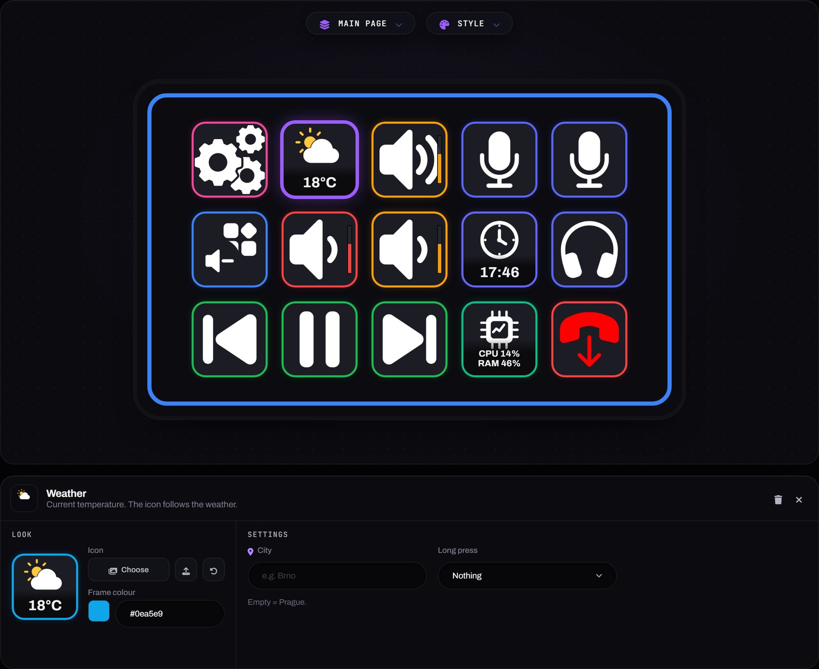
Hotkey
Record any keyboard shortcut — Ctrl+Shift+S, Win+D — and trigger it
with one tap.
Works in every application that accepts keyboard input, from Photoshop and Premiere Pro to games. No driver needed; it behaves like a real keyboard.
Folder
Group keys into sub-pages. Tapping a folder opens a page with up to fifteen more buttons — handy for separating apps, scenes or workspaces.
Each folder gets a Back key automatically.
Launch app
Start any program, file or script with one press. Pick a running process from the list or point to an executable.
Command-line arguments are supported, so a key can open a specific project or start a server.
Web / URL
Open a website, local address or deep link in your default browser.
Custom protocol links work too — a Discord channel, a Spotify playlist or a router admin page.
App volume
Control the volume of a single application — browser, game, Discord, Spotify — with volume up, volume down or mute keys.
The key shows the application's icon with a volume badge, so you always know what it controls.
Discord
Mute, deafen or leave a voice channel from the desk.
It connects through Discord's RPC. Once authorised the keys stay in sync with your voice session — the mute key turns red the moment you are muted.
Update with one click.
Open Install firmware in the app. It finds the COM port, prepares the firmware for your display and builds it.
Press Build & upload to put it on the ESP32 — no Arduino IDE and no code.
No app on this computer? The web flasher does the same from Chrome or Edge.
You are all set.
The Wdeck is assembled and the app is ready. Build your first layout and assign some keys.