Guide 1 · Build the Wdeck DIY

Build your Wdeck.

Ten steps from printed parts to a working, calibrated deck, in about two hours of work plus printing time. Setting up keys is in the app guide.

Step 01 · Prepare

Everything on the desk first.

5 min

Order the two modules, print the case and pick up five screws before you start. Keep the screen face down on something soft while you work.

  • ESP32 DevKit: WROOM-32 DevKit V1, 30 pins
  • 3.5" touchscreen: ILI9488 SPI with touch layer
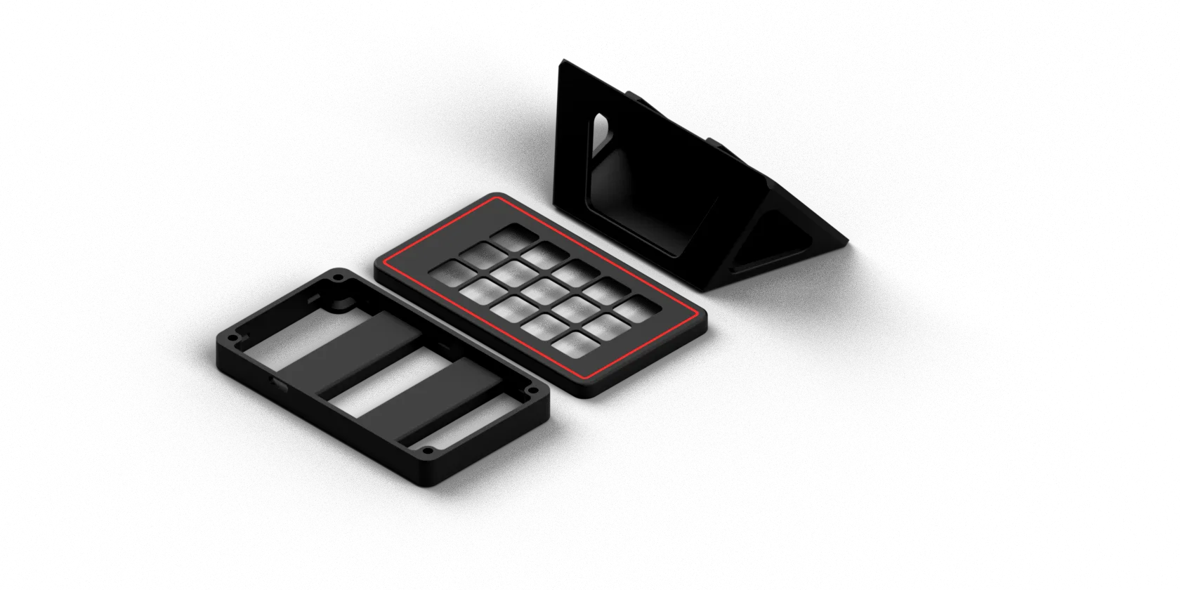
  • Printed case: bezel, shell and stand
  • 5× M3×14 countersunk screws, glue, hook-up wire
  • Tools: soldering iron, Phillips screwdriver, USB data cable
Full parts list with links →
All parts of the Wdeck DIY laid out
Step 02 · Prepare

Print the three parts.

≈ 6 h printingPETGFDM printer

PETG keeps its shape next to a warm monitor. Each part can be a different colour; the stripe on the bezel looks best in a contrasting one.

  • Layer0.2 mm
  • Infill20 % gyroid
  • SupportsBuild plate only
STL files on Printables
Step 03 · Assemble

Glue the ESP32 into the shell.

10 min + curingESP32Rear shellGlue

Line the USB connector up exactly with the opening in the rear shell, then glue the board in place. Let the glue cure fully, so the board stays put when you plug the cable in and out.

Step 04 · Assemble

Snap the screen into the bezel.

5 minFront bezelDisplay

Slide the display in from the back of the bezel until it sits flat against the window. Gentle pressure around the plastic edge snaps it in.

Never press on the middle of the panel or the touch glass, and keep the ribbon cable flat, not twisted or pinched under the frame.

Step 05 · Assemble

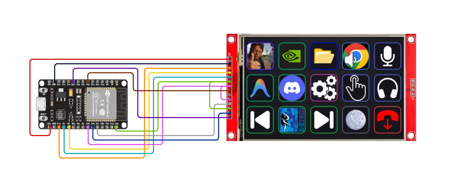
Connect eleven wires.

≈ 45 minSoldering ironHook-up wire

Solder each wire from the ESP32 pin to the display pin. MOSI and SCK go to both the screen and its touch controller. Power the display from 3V3, never 5 V.

Point at a wire in the diagram or the table to single it out, and tick each one off as you solder it. The checklist is saved in this browser.

Wiring from the ESP32 DevKit to the 3.5 inch display 3V3VCC GNDGND GPIO 15CS GPIO 4RESET GPIO 2DC / RS GPIO 23SDIT_DIN GPIO 18SCKT_CLK GPIO 32LED GPIO 21T_CS GPIO 19T_DO GPIO 27T_IRQ
Point at a wire0 of 11 connected ·
DoneWireESP32DisplayFunction
3V3VCCPower
GNDGNDGround
GPIO 15CSDisplay select
GPIO 4RESETReset
GPIO 2DC / RSData / command
GPIO 23SDI (MOSI) + T_DINSPI data, shared
GPIO 18SCK + T_CLKSPI clock, shared
GPIO 32LEDBacklight
GPIO 21T_CSTouch select
GPIO 19T_DOTouch data out
GPIO 27T_IRQTouch interrupt

Other boards: the ESP32-S3 has no GPIO 23 or 32, so it uses different pins. The desktop app shows them in its Firmware tab and builds the firmware to match.

Step 06 · Assemble

Tuck the wires into the channels.

10 minTweezers

Lay the wires along the side channels inside the shell. A loose bundle can stop the case from closing or pinch a wire into a short.

Keep the fast lines (SCK, MOSI, CS) away from VCC and GND to avoid touch noise and display glitches. Leave the front open for now: calibration comes before closing.

Wires between the ESP32 and the display
Step 08 · Bring it to life

Calibrate the touch screen.

2 minStylus or fingertip

On the first start the Wdeck asks for calibration: tap the highlighted keys: the four corners, then the one in the middle. The screen says Touch ready when it is done.

The result is stored on the ESP32 and survives restarts. If touch ever feels off, press Calibrate in the app under Settings → General.

Step 09 · Bring it to life

Close the case.

5 min5× M3 screwsScrewdriver

Place the bezel on the shell, check that no wire is pinched, and fix it with four M3 screws. The fifth screw holds the deck on the stand. Push the four rubber feet into the pockets under the stand.

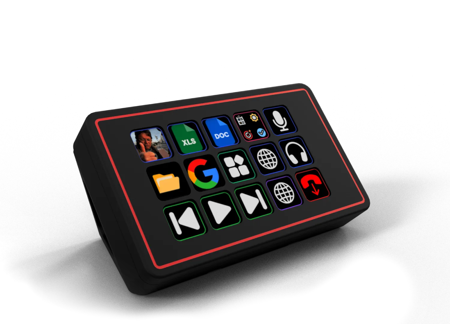
The finished Wdeck DIY
Step 10 · Done

The hardware is done.

Your Wdeck is assembled and calibrated. Install the app, pick your deck and start setting up keys.